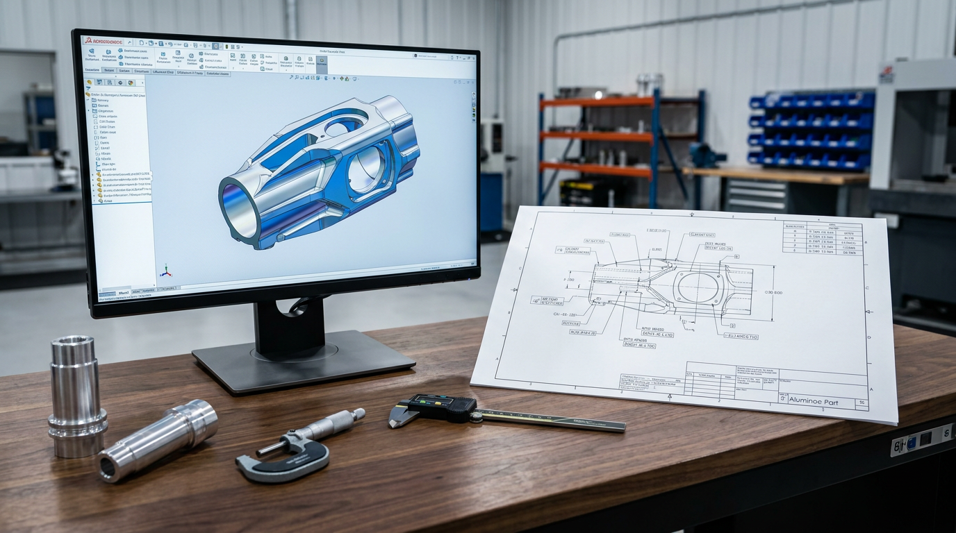
Submitting a Request for Quotation (RFQ) for CNC machined parts seems straightforward: send a 3D CAD model to a machine shop and wait for a price. However, incomplete or ambiguous technical packages frequently lead to bloated pricing buffers, extended lead times, or back-and-forth engineering emails.
When a machinist receives an incomplete RFQ, they must either make conservative assumptions that increase cost estimates or halt the quoting queue to request missing specifications. This guide outlines every technical, material, quality, and commercial element required to build a thorough CNC machining RFQ package that delivers fast turnaround times and accurate pricing.
QUICK ANSWER: WHAT SHOULD A CNC MACHINING RFQ INCLUDE?
A complete CNC machining RFQ package provides suppliers with full geometric data, material definitions, precision bounds, and commercial terms. Providing these details upfront eliminates ambiguity and allows machine shops to program CAM toolpaths and calculate machine cycle times with confidence.
THE ESSENTIAL INFORMATION FOR A COMPLETE CNC MACHINING RFQ
At a minimum, every production-ready CNC machining RFQ package must contain six core technical components:
3D CAD Model: Neutral solid model format (
.STEPor.STP) for CAM programming, fixture design, and 3D geometric calculation.2D Engineering Drawing: Fully dimensioned
.PDFdrawing detailing critical tolerances, thread callouts, surface roughness, chamfers, and notes.Material Specification: Exact material alloy grade and temper condition (e.g., Aluminum 6061-T6, 316L Stainless Steel, Titanium Grade 5) rather than a generic material family.
Surface Finish & Post-Processing: Required surface roughness (Ra value) and secondary operations such as anodizing, passivation, or heat treatment.
Quantity & Production Scope: Order volume (prototype, pilot run, or production batch) alongside Estimated Annual Usage (EAU) for volume pricing.
Inspection & Quality Compliance: Certification requirements, First Article Inspection (FAI), CMM inspection reports, or material test reports (MTR).
WHY COMPLETE RFQ INFORMATION IMPROVES QUOTE ACCURACY AND SPEED
Machine shops use algorithmic quoting software and experienced estimators to determine machine setup time, cycle time, tooling wear, and raw stock costs. When an RFQ is missing critical tolerances or surface finish specifications, estimators apply worst-case assumptions or pause processing entirely.
Key Takeaway: Providing a complete 3D CAD model paired with a detailed 2D engineering drawing reduces quoting turnarounds from weeks to 24–48 hours and prevents post-award price revisions.
CNC MACHINING RFQ VS. CNC MACHINING QUOTE
It is essential to distinguish between the buyer’s input and the supplier’s output:
CNC Machining RFQ: The comprehensive engineering and commercial request prepared by the buyer detailing part geometry, quality standards, and purchasing parameters.
CNC Machining Quote: The binding financial and operational offer returned by the supplier, detailing piece price, tooling/setup charges, lead times, DFM feedback, and commercial terms.
WHAT IS A CNC MACHINING RFQ?
A Request for Quotation (RFQ) for CNC machining is a formal engineering procurement document that invites machine shops to bid on manufacturing custom metal or plastic components.
PURPOSE OF A REQUEST FOR QUOTATION FOR CNC MACHINED PARTS
The primary objective of a CNC machining RFQ is to transmit complete manufacturing intent. Unlike off-the-shelf catalog items, custom machined parts require mill-turn centers, 3-axis, or 5-axis CNC machines to cut raw billet or bar stock according to custom toolpaths. The RFQ provides the machine shop with all parameters necessary to assess feasibility, run DFM (Design for Manufacturability) checks, and estimate cycle costs.
WHAT INFORMATION CNC SUPPLIERS USE TO REVIEW AN RFQ
When an estimator reviews an RFQ package, they analyze five cost-driving dimensions:
Review Dimension | Estimator Analysis & Machine Shop Impact |
|---|---|
Geometry & Accessibility | Determines required machine axis count (3-axis vs. 5-axis), setup rotations, and special cutting tools. |
Material Machinability | Calculates cutting speeds, feeds, tool wear rates, and raw material stock costs. |
Tolerances & GD&T | Dictates machine choice, thermal control needs, and secondary grinding or honing operations. |
Surface Finish & Treatments | Identifies post-machining chemical processing, plating, or manual deburring requirements. |
Volume & Batching | Spreads fixed setup and programming costs across the production run. |
HOW RFQ QUALITY AFFECTS QUOTATION ACCURACY AND LEAD TIME
High-quality RFQs pass directly into the supplier’s CAM environment for rapid toolpath simulation. Conversely, vague RFQs introduce financial risk for the supplier. To protect their margins against unexpected machining complexities, suppliers insert contingency pricing buffers. Clear specifications remove these risk markups, yielding lower piece prices and realistic production lead times.
TECHNICAL FILES REQUIRED FOR A CNC MACHINING RFQ
Modern precision manufacturing relies on a dual-file strategy: a 3D CAD model for digital geometry processing and a 2D engineering drawing for technical intent and inspection standards.
STANDARD 3D CAD FORMATS FOR CNC MACHINING
Always export 3D CAD models using universally accepted, neutral solid formats. Native CAD files from SolidWorks (.sldprt), Autodesk Inventor (.ipt), or PTC Creo (.prt) can suffer from version incompatibility or feature-tree corruption when opened in different CAM software packages.
STEP (
.step/.stp): The universal industry standard for 3D digital manufacturing. Protocols like AP214 and AP242 preserve precise solid geometry, color-coded surfaces, and semantic Product Manufacturing Information (PMI).IGES (
.igs/.iges): A legacy surface-based format. While widely compatible, IGES files can suffer from stitched surface gaps or trimmed surface errors, requiring manual repair in CAM software.Parasolid (
.xₜ/.x b): A robust solid modeling kernel format ideal for high-precision 5-axis machining environments.
REVISION-CONTROLLED 2D ENGINEERING DRAWINGS
While 3D CAD models define overall geometry, they do not inherently convey manufacturing details like internal thread pitch, press fits, surface roughness, or critical datums. A 2D engineering drawing in vector .PDF format acts as the legally binding technical contract.
Key elements required on every 2D drawing include:
Title block with part number, part title, and explicit revision letter/number.
Primary, secondary, and tertiary datums for measurement alignment.
Explicit dimensions for tight tolerances, hole depths, and thread callouts (e.g.,
M6x1.0 - 6H ↧ 12mm).General tolerance block (e.g., ISO 2768-mK) and surface finish notes.
CAD MODEL AND DRAWING REVISION CONSISTENCY
Discrepancies between the 3D model geometry and the 2D drawing dimensions are among the leading causes of machining delays. If an engineer updates a hole location in the 2D drawing but forgets to re-export the 3D STEP file, the supplier’s CAM program will cut the part based on the outdated STEP geometry.
⚠️ Warning: Always include a clear precedence clause in the title block of your 2D drawing stating which file governs in the event of a discrepancy (e.g., “3D STEP file governs nominal geometry; 2D PDF drawing governs tolerances, threads, and surface finishes”).
WHEN STEP, IGES, DWG, OR DXF FILES ARE NEEDED
Different manufacturing operations require different file extensions:
STEP / IGES: Essential for 3-axis, 4-axis, and 5-axis CNC milling, turning, and mill-turn operations.
DXF / DWG: Required for 2D profile cutting operations such as CNC waterjet, laser cutting, sheet metal blanking, or 2D wire EDM.
ASSEMBLY DRAWINGS AND RELATED REFERENCE FILES
For parts that require press-fit bushings, helicoil inserts, or sub-assembly work, supply an exploded assembly drawing alongside a Bill of Materials (BOM). Specify whether hardware items are buyer-furnished or supplier-sourced.
MATERIAL AND SURFACE FINISH REQUIREMENTS
Material selection directly influences cutting speeds, tool life, and raw material costs. Vague material callouts like “Aluminum” or “Stainless Steel” prevent shops from generating accurate estimates.
MATERIAL GRADE, ALLOY, TEMPER, AND CONDITION
Always specify the complete alloy designation, temper, and thermal condition:
Aluminum: Specify
6061-T6(standard structural),7075-T651(high strength aerospace), or2024-T3instead of generic “Aluminum”.Stainless Steel: Specify
304(general corrosion resistance),316L(marine/medical grade), or17-4 PH H900(precipitation hardened) rather than “Stainless”.Steels & Alloys: Specify
4140 Annealedor4340 Normalized.Plastics: Specify
Delrin 150(Unfilled Acetate),PEEK 450G, orPTFE(Teflon).
RAW MATERIAL SIZE AND STOCK REQUIREMENTS
If your component requires specific grain orientation, oversized raw billet for stress relief, or customer-supplied specialized forgings, note these constraints on the RFQ. Indicate whether mill test reports (MTR) demonstrating traceability to original material melts are required.
SURFACE FINISH AND SURFACE ROUGHNESS SPECIFICATIONS
CNC machining leaves visible tool marks along toolpath passes. Surface roughness is specified using the Roughness Average (Ra) value in micrometers (µ m) or microinches (µ in):
AS-MACHINED (Ra 3.2 µm / 125 µin) → Standard CNC milling finish FINE MACHINED (Ra 1.6 µm / 63 µin) → Smoother toolmarks, light pass PRECISION GROUND (Ra 0.8 µm / 32 µin) → Bearing faces, seal surfaces
Ra 3.2 µ m (125 µ in): Standard as-machined finish. Cost-effective for structural internal parts.
Ra 1.6 µ m (63 µ in): Fine machined finish. Ideal for mating surfaces and tight static joints.
Ra 0.8 µ m (32 µ in): High-precision finish requiring slower feeds, light finishing passes, or surface grinding.
ANODIZING, PLATING, HEAT TREATMENT, AND OTHER SECONDARY PROCESSES
Post-processing adds lead time and cost. State all secondary finish parameters explicitly:
Anodizing: Specify type and class per MIL-A-8625 (e.g., Type II Class 2 Black Anodize or Type III Hardcoat Anodize 0.002″ thickness). Note critical dimensions that apply before or after plating.
Plating & Passivation: Specify Electroless Nickel Plating (MIL-C-26074) or Stainless Steel Passivation (ASTM A967).
Heat Treatment: Indicate target hardness on the Rockwell C scale (e.g., Heat treat to 40–45 HRC).
Masking Requirements: Mark ground points, internal threads, or precision bores that must be masked during anodizing or painting.
TOLERANCES, GD&T, AND QUALITY REQUIREMENTS
Tolerances dictate how much a part’s physical dimensions can deviate from the nominal 3D CAD geometry. Tighter tolerances exponentially increase machining costs by requiring precision machine tools, controlled ambient temperatures, and specialized inspection.
Cost Factor vs Tolerance Tightness
Cost Multiplier
5x / ±0.005 mm / ±0.0002″ 4x / 3x /—–‘ ±0.025 mm / ±0.001″ 2x /——‘ 1x ————————-‘ ±0.1 mm / ±0.004″ Standard ISO 2768-m ► Tolerance Tightness
GENERAL TOLERANCE STANDARDS AND ISO 2768
Rather than dimensioning every feature individually, engineering drawings use general tolerance title block standards. The most widespread standard in international CNC machining is ISO 2768.
ISO 2768 consists of two parts:
ISO 2768-1: Covers linear and angular dimensions across four classes:
f(fine),m(medium),c(coarse), andv(very coarse).ISO 2768-2: Covers geometrical tolerances across three classes:
H,K, andL.
Specifying ISO 2768-mK in your title block establishes medium linear tolerances (± 0.1 mm for dimensions up to 30 mm) and medium geometric controls across all un-dimensioned features.
CRITICAL DIMENSIONS AND TIGHT TOLERANCES
Reserve tight tolerances (such as ± 0.01 mm or ± 0.0005 in) strictly for functional features like bearing seats, dowel pin alignment holes, or seal grooves. Flag critical-to-function dimensions using inspection balloons or boxed callouts on the 2D drawing.
GD&T DATUMS AND FEATURE CONTROL REQUIREMENTS
Geometric Dimensioning and Tolerancing (GD&T) per ASME Y14.5 or ISO 1101 defines allowable variation in geometric relationships rather than simple distance ranges.
Feature Control Frame Example: Position Symbol | Ø 0.05 | Datum A | Datum B
Properly configured GD&T uses primary (A), secondary (B), and tertiary (C) datums to mirror physical assembly mounting points. This allows the shop to design fixtures that match functional real-world alignment.
THREAD, HOLE, RADIUS, AND CHAMFER SPECIFICATIONS
Provide explicit callouts for cut or thread features:
Threads: State thread series, class of fit, and depth (e.g.,
1/4-20 UNC-2B ↧ 0.50 inorM5x0.8 - 6H ↧ 10mm). Indicate if threads must be cut after anodizing.Internal Corners: Avoid sharp internal vertical corners. Specify an internal corner radius (R ≥ 1/3 × cavity depth) so suppliers can cut cavities using standard end mills without custom EDM electrodes.
INSPECTION REPORTS, CMM, CERTIFICATIONS, AND COMPLIANCE DOCUMENTS
Define required quality control deliverables on the initial RFQ:
Material Test Report (MTR): Verifies chemical and mechanical properties from the material mill.
Certificate of Conformance (CoC): Standard vendor document attesting that parts meet drawing specifications.
First Article Inspection (FAI): Comprehensive inspection report (such as AS9102) verifying every dimension on the 2D drawing for initial pilot units.
CMM Inspection Report: Coordinate Measuring Machine dimensional mapping for high-precision components.
QUANTITY, PRODUCTION, AND DELIVERY INFORMATION
Manufacturing setup costs—including CAD/CAM programming, machine fixture design, tool loading, and material block preparation—are fixed charges. Order quantities significantly affect per-unit pricing.
INITIAL QUANTITY, BATCH SIZE, AND EXPECTED ANNUAL USAGE
When submitting an RFQ, provide three distinct quantity figures whenever applicable:
Initial Order Quantity: The immediate batch size to be produced (e.g., 50 pieces).
Batch Production Sizes: Planned release schedule (e.g., 50 pieces per quarter).
Estimated Annual Usage (EAU): Total anticipated annual volume (e.g., 200 pieces/year).
Highlighting EAU allows suppliers to amortize fixture design investments and negotiate bulk raw material discounts, resulting in lower piece quotes.
PROTOTYPE, LOW-VOLUME, AND PRODUCTION REQUIREMENTS
Specify the operational tier of your project:
Prototype (1–10 pcs): Prioritizes speed and minimal soft tooling costs.
Low-Volume Production (10–500 pcs): Focuses on unit cost optimization and soft fixture repeatability.
Mass Production (1,000+ pcs): Justifies modular multi-part tombstone fixtures, custom cutting tools, and automated cell loading.
REQUIRED DELIVERY DATE AND SHIPPING DESTINATION
Provide targeted delivery deadlines alongside the delivery address and ZIP code. State whether delivery deadlines represent ship dates from the factory floor or arrival dates at your facility.
PACKAGING, LABELING, AND LOGISTICS REQUIREMENTS
Machined parts with delicate cosmetic anodizing or tight sealing faces require protective handling during transport:
Individual bubble wrapping or custom foam compartmentalized trays.
Anti-static bagging for electronics enclosures.
Custom barcode labeling, part marking (laser etching / dot peen), or military-grade packaging standards.
RFQ BEST PRACTICES BEFORE SUBMISSION
Executing pre-submission verification prevents unnecessary design iteration loops after submitting your RFQ package.
PRE-SUBMISSION DFM AND MANUFACTURABILITY CHECKS
Conduct a preliminary DFM (Design for Manufacturability) review prior to sending files out for quote:
Deep Cavities: Ensure pocket depth does not exceed 4x the tool diameter.
Wall Thickness: Maintain minimum wall thickness above 0.8 mm for aluminum and 1.5 mm for plastics to prevent chatter and thermal warping.
Tool Access: Verify that cutting tools can physically reach internal pockets without colliding with part walls.
IDENTIFY CRITICAL FEATURES AND NON-NEGOTIABLE REQUIREMENTS
Avoid over-specifying tolerances across non-critical outer boundaries. Clearly separate non-negotiable functional requirements (such as bearing bore runout) from flexible cosmetic features.
DEFINE REVISION STATUS AND APPROVED DOCUMENTS
Establish strict file naming discipline. Ensure the 3D STEP file name, 2D PDF drawing title block, and email RFQ subject line share identical part numbers and revision codes (e.g., PART-10482-REV-B.STEP and PART-10482-REV-B.PDF).
INCLUDE PART FUNCTION OR APPLICATION INFORMATION WHEN RELEVANT
Briefly stating the end-use application (e.g., “High-vacuum optical housing” or “Outdoor bracket subject to salt spray”) helps application engineers suggest alternative alloys, cost-effective surface finishes, or minor DFM modifications that lower costs without compromising part function.
COMMON CNC MACHINING RFQ MISTAKES THAT CAUSE DELAYS
Avoiding frequent RFQ oversights ensures your package moves quickly through supplier quoting queues.
INCOMPLETE CAD FILES OR MISSING 2D DRAWINGS
Submitting a 3D STEP file without an accompanying 2D PDF drawing forces machine shops to guess thread requirements, surface finishes, and allowable tolerances. Conversely, submitting only a paper 2D drawing requires estimators to manually reconstruct 3D CAD geometry before programming CAM software.
CAD MODEL AND DRAWING DISCREPANCIES
When a 3D model geometry differs from the 2D drawing dimensions, suppliers must freeze the quote to request technical clarification. Always run an automated geometry-to-drawing verification in your CAD software before exporting.
UNSPECIFIED MATERIAL, TOLERANCES, OR SURFACE FINISH
Vague callouts like “Aluminum” or “As Machined” lead to ambiguous quotes. One shop may quote low-cost 6061-O aluminum with a rough Ra 6.3 finish, while another quotes premium 6061-T6 with a fine Ra 1.6 finish, making side-by-side price comparison impossible.
MISSING THREAD, HOLE, OR CRITICAL FEATURE DETAILS
3D STEP models do not represent physical thread geometry—they display smooth cylinders representing minor or major thread diameters. Without a 2D PDF callout specifying thread pitch, depth, and thread class, machine shops cannot quote tapping operations accurately.
DESIGN CHANGES AFTER THE RFQ HAS BEEN SUBMITTED
Sending revised CAD files midway through the quoting process resets the estimator’s workflow. Finalize your CAD geometry and revision status prior to sending out RFQ packages.
Pro Tip: For technical teams managing complex documentation, leveraging an AI content and documentation automation platform helps standardize engineering release workflows, creating consistent RFQ technical packages and technical blog content creation workflows that document internal design standards clearly.
CNC MACHINING RFQ CHECKLIST FOR ENGINEERS AND BUYERS
Use this three-part checklist to audit your technical package prior to submitting an RFQ to CNC machining suppliers.
CAD, DRAWING, REVISION, AND TECHNICAL DATA CHECKLIST
3D CAD Model: Exported as a neutral
.STEPor.STPfile (AP214 or AP242).2D Engineering Drawing: Vector
.PDFfile with complete orthogonal and section views.Revision Consistency: Part number and revision match across 3D model, 2D drawing, and RFQ form.
Precedence Clause: Title block states whether 3D STEP or 2D PDF governs nominal geometry vs. tolerances.
2D File Formats: DXF or DWG files included if profile cutting or laser blanking is required.
MATERIAL, TOLERANCE, FINISH, AND QUALITY CHECKLIST
Material Definition: Complete material grade, alloy designation, temper, and condition specified.
General Tolerances: ISO 2768 class (e.g.,
ISO 2768-mK) or title block tolerance matrix established.Critical Tolerances & GD&T: Functional features explicitly dimensioned with ASME Y14.5 feature control frames.
Thread Specifications: Thread series, pitch, depth, class of fit, and post-plating status defined.
Surface Roughness: Roughness Average (Ra) specified in µ m or µ in.
Secondary Processes: Anodizing, plating, heat treatment, and masking requirements noted with standards.
Quality Deliverables: MTR, CoC, FAI, or CMM measurement reports requested upfront.
QUANTITY, DELIVERY, PACKAGING, AND COMMERCIAL REQUIREMENTS CHECKLIST
Production Quantities: Initial batch size, release schedule, and Estimated Annual Usage (EAU) stated.
Timeline & Schedule: Target factory ship date or arrival date indicated with destination address/ZIP.
Packaging Standards: Protective trays, anti-static wrapping, or custom barcode labeling specified.
Commercial Terms: Incoterms, payment expectations, and special quality compliance standards noted.
CNC MACHINING RFQ FAQS
WHAT INFORMATION SHOULD I INCLUDE IN A CNC MACHINING RFQ?
A complete CNC machining RFQ must include a 3D CAD model (.STEP), a 2D engineering drawing (.PDF), exact material grade and temper, surface finish specs (Ra), critical tolerances or GD&T, order quantities, and delivery/quality requirements.
WHAT CAD FILE FORMAT IS BEST FOR A CNC MACHINING RFQ?
The .STEP format (AP214 or AP242) is the industry standard for 3D CAD models. It preserves solid geometry across different CAM platforms without feature tree corruption.
DO I NEED A 2D DRAWING FOR A CNC MACHINING RFQ?
Yes. 2D drawings are required to define features that 3D STEP files cannot fully convey, such as thread callouts, critical tolerances, surface roughness (Ra), GD&T datums, and specific inspection requirements.
WHAT MATERIAL INFORMATION SHOULD I PROVIDE IN AN RFQ?
Provide the full alloy grade, temper, and condition—such as Aluminum 6061-T6 or Stainless Steel 316L—rather than a generic material family like “aluminum” or “steel.”
SHOULD I INCLUDE GD&T IN A CNC MACHINING RFQ?
Yes, use GD&T (per ASME Y14.5) on critical functional features. GD&T communicates functional datums and allowable geometric variation clearly, preventing over-tolerancing on non-critical dimensions.
HOW DOES QUANTITY AFFECT A CNC MACHINING RFQ?
Higher order volumes and Estimated Annual Usage (EAU) lower piece prices by spreading fixed CAD/CAM programming, machine setup, and custom tooling costs across more units.
WHAT CAUSES DELAYS IN THE CNC MACHINING RFQ PROCESS?
Missing 2D drawings, ambiguous material grades, missing thread details, drawing-to-CAD file discrepancies, and mid-quote design changes are the leading causes of quoting delays.
HOW CAN I GET A FASTER AND MORE ACCURATE CNC MACHINING QUOTE?
Submit a clean STEP file paired with a vector PDF drawing, specify exact materials and surface finishes, define clear general tolerances (ISO 2768-mK), and highlight functional critical dimensions upfront.
CONCLUSION: PREPARE A COMPLETE CNC MACHINING RFQ BEFORE REQUESTING A QUOTE
Taking the time to compile a comprehensive, unambiguous CNC machining RFQ package pays immediate dividends. By supplying machine shops with clear 3D STEP geometry, fully dimensioned 2D PDF drawings, exact material tempers, and explicit quality requirements, engineering teams eliminate guesswork and prevent costly price markups.
Before submitting your next project for quote, audit your technical documentation against the RFQ checklist in this guide to secure accurate pricing, rapid quoting turnarounds, and reliable manufacturing execution.